

In modern manufacturing, where precision and efficiency are paramount, end milling stands out as a fundamental and versatile process. As a cornerstone of CNC (Computer Numerical Control) machining, it is the go-to method for creating a vast array of features on components for critical industries, from aerospace to medical devices. This guide offers a comprehensive exploration of end milling, covering its core principles, tooling, workflow, and the optimization strategies that define high-quality manufacturing.
What is End Milling? The Foundation of Precision Machining
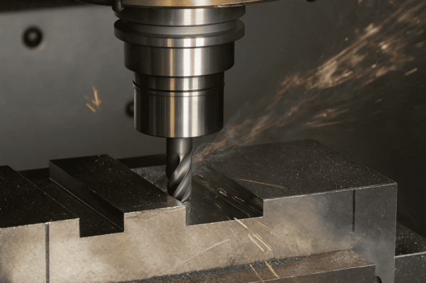
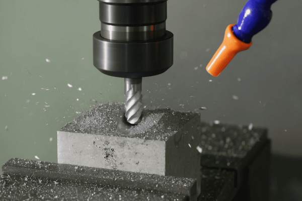
End milling is a versatile subtractive manufacturing process that uses a rotating, multi-toothed cutting tool—an end mill—to precisely remove material from a workpiece. While milling has existed since the 1800s, modern CNC end milling represents a peak of technological evolution in shaping materials.
The Core Purpose: From Material Removal to Feature Creation
The fundamental purpose of end milling is to precisely shape materials to meet predetermined dimensions and create specific geometric features. It is employed to machine a diverse range of features, including slots, pockets, holes, complex 3D contours, and die cavities. The process is capable of both heavy material removal (roughing) and creating parts with high-quality surface finishes and tight dimensional tolerances, sometimes as fine as ±0.002 mm.
End Milling vs. Other Machining Operations: A Comparative Analysis
End milling’s unique strengths become clear when compared to other common machining operations. Its versatility lies in the design of the end mill, which features cutting edges (flutes) on both its periphery (sides) and its end face, enabling multi-directional cutting.
- Versus Drilling: A drill bit is designed for axial cutting—plunging straight down to create a hole. While some end mills can also plunge vertically, their main strength is cutting radially (sideways), which allows them to create features like slots and pockets that drilling cannot.
- Versus Face Milling: Face milling uses a large-diameter cutter to machine a broad, flat surface, focusing on achieving flatness over a wide area. End milling, by contrast, is focused on creating specific, often intricate, features like contours and profiles.
- Versus Turning: In turning, the workpiece rotates while a stationary tool removes material, making it ideal for creating cylindrical parts. In milling, the tool rotates while the workpiece is moved along a controlled path, enabling the creation of non-symmetrical and geometrically complex parts.
What Are End Mills? A Deep Dive into the Anatomy of the Tool
The success of any end milling operation is tied to the cutting tool. An end mill is a highly engineered tool where every feature is designed for a specific purpose. Understanding these features is crucial for selecting the right tool, which directly impacts the quality, efficiency, and cost of the final component.
Anatomy of an End Mill: The Language of the Cutter
- Flutes: These sharp, helical grooves shear material from the workpiece and evacuate the resulting chips away from the cutting zone.
- Helix Angle: The angle of the flutes relative to the tool’s centerline. A high helix angle (e.g., 45°) creates a smoother cut, while a low helix angle provides a stronger cutting edge for roughing or hard materials.
- Shank: The cylindrical, non-cutting portion of the tool that is gripped by the machine’s tool holder.
- Cutter Dimensions: Key dimensions include cutter diameter, length of cut, and overall length. A core principle is to use the shortest tool possible for a given job to minimize deflection and vibration (chatter).
- Center-Cutting vs. Non-Center-Cutting: Center-cutting end mills have cutting edges that extend to the center of the tool’s tip, allowing them to plunge vertically into solid material. Non-center-cutting end mills cannot plunge and can only be used for side milling or entering a pre-existing hole.
Classification by Geometry: Choosing the Right Shape for the Job
The geometry of an end mill’s tip determines the shape of the features it can create.
- Square (Flat) End Mill: Used for general-purpose slotting, profiling, and pocketing, it creates sharp, 90° corners and flat-bottomed features.
- Ball Nose End Mill: Ideal for 3D contouring, surface sculpting, and creating fillets, this tool produces smooth, blended surfaces with no sharp corners and is essential for molds and dies.
- Corner Radius (Bull Nose) End Mill: Used for milling pockets with a specified corner radius and for high-feed finishing, its rounded corners strengthen the cutting edge, preventing chipping and extending tool life.
- Roughing End Mill (Hog Mill): Designed for aggressive, high-volume material removal, its serrated edges break chips into small pieces, which reduces vibration during heavy cuts.
- Finishing End Mill: Used for final passes to achieve tight tolerances and a superior surface finish, it typically has more flutes and a higher helix angle for a smoother cutting action.
- Specialty Mills (Taper, V-Bit, etc.): These are designed for a single, specialized geometric task, such as creating angled slots (tapered), chamfers, or engravings (V-bit).
Classification by Material and Coating: The Science of Durability
The material of the end mill and its coating are chosen based on the workpiece material and desired performance.
- Tool Substrates:
- High-Speed Steel (HSS): Affordable and tough, but lacks heat resistance for high-speed machining.
- Cobalt (HSSE): HSS with added cobalt for better heat and wear resistance, suitable for materials like stainless steel.
- Solid Carbide: The industry standard for high-performance CNC machining. It is extremely hard and heat-resistant, allowing for much faster cutting speeds.
- Performance-Enhancing Coatings: Coatings are micro-thin layers that enhance an end mill’s hardness, heat resistance, and lubricity.
- Aluminum & Non-Ferrous: For these materials, Carbide is the recommended substrate, with optimal coatings being DLC (Diamond-Like Carbon) or ZrN (Zirconium Nitride).
- Low-Carbon & Alloy Steels: Carbide is the preferred substrate, best paired with TiAlN (Titanium Aluminum Nitride) or AlTiN coatings.
- Stainless Steels: Use a Carbide substrate with AlTiN or AlCrN (Aluminum Chromium Nitride) coatings.
- Titanium & High-Temp Alloys: A Carbide substrate is recommended, along with AlTiN or AlCrN coatings.
- Cast Irons: For cast irons, a Carbide substrate is best, with recommended coatings including TiAlN, AlTiN, or TiCN (Titanium Carbonitride).
- Plastics & Composites: Depending on the application, either Carbide or HSS can be used, often with an Uncoated or DLC finish.
The Flute Count Conundrum: Balancing Strength and Chip Evacuation
The number of flutes on an end mill involves a trade-off between chip evacuation space and cutting edge engagement.
- Fewer Flutes (2-3): Provide excellent space for chip evacuation, essential for soft materials like aluminum that produce large chips.
- More Flutes (4-8+): Lead to a smoother surface finish and allow for higher feed rates in harder materials. The increased number of flutes also adds to the tool’s rigidity.
How Does the End Milling Process Work? From Digital Design to Physical Part
The end milling process is a sophisticated workflow that transforms a digital concept into a tangible component.
The Digital Workflow: CAD to CAM
The process begins with a 3D Computer-Aided Design (CAD) model, which acts as the digital blueprint. This model is imported into Computer-Aided Manufacturing (CAM) software, where a programmer defines the machining strategy, including tool selection, cutting parameters, and toolpaths. The CAM software then generates the G-code that directs the CNC machine.
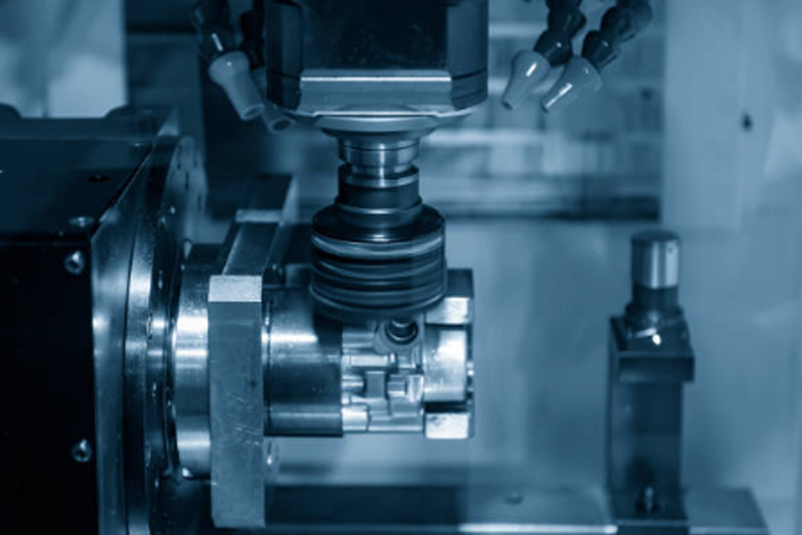
Machine Setup and Execution
- Workholding: The raw material is securely fastened to the machine’s table. Rigid workholding is non-negotiable, as any movement will compromise accuracy.
- Tool Mounting: The selected end mill is placed into a precision tool holder and loaded into the machine’s spindle.
- Execution: The G-code program is loaded, and the machine executes the program, moving the tool and workpiece relative to each other to cut the part.
The Mechanics of the Cut: Roughing, Semi-Finishing, and Finishing
A part is typically machined in distinct stages:
- Roughing: The initial stage focused on removing the bulk of unwanted material as quickly as possible.
- Semi-finishing: An intermediate step that refines the part’s shape and prepares surfaces for the final cut.
- Finishing: The final pass, performed at slower feed rates and a lighter depth of cut, to achieve the final dimensional accuracy and specified surface finish.
Critical Insight: Climb Milling vs. Conventional Milling
One of the most fundamental strategic decisions is the choice between climb and conventional milling, which refers to the relationship between the cutter’s rotation and the workpiece feed direction.
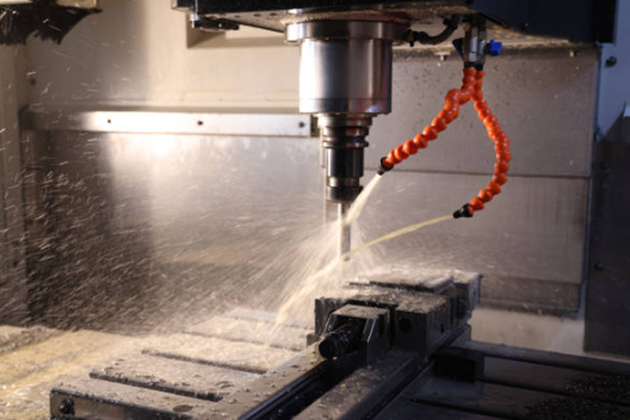
- Conventional Milling (Up Milling): The cutter rotates against the direction of feed. The chip starts at zero thickness and increases. This was the required method on older, manual machines because it helped eliminate the effects of backlash (play) in the machine’s lead screws. However, it tends to rub at the start of the cut, generating more heat, causing faster tool wear, and pushing chips in front of the cutter, where they can be re-cut, degrading the surface finish.
- Climb Milling (Down Milling): The cutter rotates with the direction of feed. The chip starts at maximum thickness and thins out. This is the universally preferred method on modern, rigid CNC machines that use backlash-free ball screws. It produces a superior surface finish, transfers heat more effectively into the chip (which protects the tool and workpiece), extends tool life, and creates downward cutting forces that help hold the workpiece securely in the fixture. Using climb milling on a machine with backlash can be catastrophic, as the tool can violently “climb” into the part and break.
What Are the Main Applications of End Milling? Shaping Critical Industries
The versatility and precision of end milling make it indispensable across numerous high-stakes industries where component failure is not an option.
- Aerospace and Defense: End milling is used to machine lightweight, high-strength materials like titanium and advanced aluminum alloys into flight-critical components such as aircraft structural parts, engine components, and turbine blades.
- Automotive: The process is fundamental to producing durable, high-performance parts like engine blocks, transmission cases, and complex suspension components.
- Medical and Dental: End milling shapes medical-grade titanium and stainless steels into life-sustaining devices like orthopedic implants, custom dental prosthetics, and intricate surgical instruments.
- Other Key Industries: Applications also include creating high-precision molds and dies, custom electronic enclosures and heatsinks, and components for the energy sector.
What Are the Advantages of End Milling? Precision, Versatility, and Efficiency
The widespread adoption of end milling is driven by a powerful combination of technical benefits.
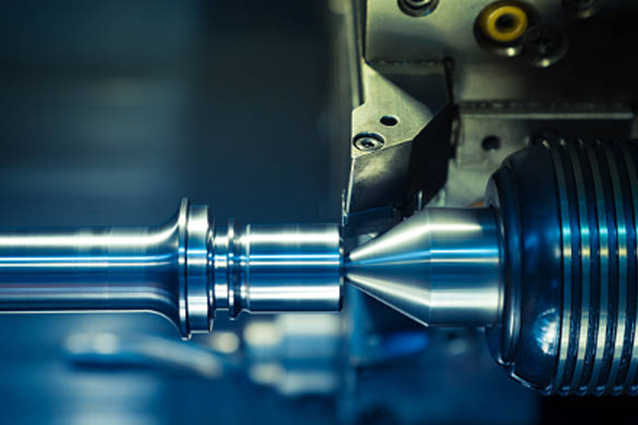
- Unmatched Precision and Tight Tolerances: Modern CNC end milling delivers exceptional accuracy and repeatability, consistently producing parts with tight tolerances essential for complex assemblies. Precision can range from a standard ±0.05 mm to as fine as ±0.002 mm.
- Extraordinary Geometric Versatility: The multi-axis capability of the tool allows for the creation of an almost limitless variety of shapes and features, including deep pockets, intricate slots, and complex 3D contours.
- Superior Surface Finish Capabilities: The process can yield exceptionally smooth surface finishes, sometimes as low as Ra 0.4 µm, often eliminating the need for costly secondary operations like grinding or polishing.
- Efficiency and Broad Material Compatibility: End milling can achieve high material removal rates, reducing cycle times and costs. It is also compatible with a vast spectrum of materials, from soft plastics to hardened tool steels and exotic superalloys.
What Factors Influence End Milling Performance?
Achieving a perfect cut involves balancing a complex system of interconnected variables.
- The “Big Three” Cutting Parameters:
- Cutting Speed (SFM/RPM): The speed of the tool’s cutting edge across the material. An incorrect speed can cause excessive heat, tool wear, or rubbing.
- Feed Rate (IPM/FPT): The speed at which the tool advances into the workpiece. It governs the material removal rate and influences surface finish.
- Depth of Cut (DOC & WOC): The axial depth (DOC) and radial width (WOC) of the cut. These parameters determine the cutting forces and chip load.
- The Stability Triangle: The quality of any milled part is built upon a foundation of rigidity.
- Machine Rigidity: The inherent stiffness of the CNC machine itself.
- Workholding Rigidity: How securely the workpiece is clamped.
- Tooling Rigidity: The stiffness of the end mill and its holder.
- Tool Wear and Material Machinability:
- Tool Wear: Natural wear on the cutting edges increases cutting forces and degrades surface finish. Tools must be monitored and replaced before quality suffers.
- Material Machinability: Every material behaves differently, dictating the optimal cutting strategy. For example, aluminum requires sharp tools and high speeds, while titanium needs lower speeds but a consistent, aggressive chip load.
How to Optimize End Milling for Best Results?
Optimization involves applying specific strategies to manage the variables discussed above.
Strategic Tooling and Parameter Tuning
- For Aluminum: Use 2 or 3-flute carbide end mills with a high helix angle and polished flutes. Coatings like DLC or ZrN are ideal. Run at very high speeds and feed rates with ample coolant or air blast.
- For Steels (Low-Carbon to Alloy): Use 4-flute (or more) carbide end mills with a robust, heat-resistant coating like TiAlN or AlTiN. Use more moderate parameters and climb milling.
- For Stainless Steel & Titanium: These materials require 4 or 5-flute, high-performance carbide end mills with advanced coatings (AlTiN, AlCrN). Employ lower cutting speeds to manage heat but maintain a healthy chip load. High-pressure coolant is essential.
Advanced Toolpath Strategies and Troubleshooting
Modern CAM software enables intelligent toolpaths like High-Efficiency Milling (HEM), which uses a small radial width of cut but a deep axial depth of cut to maintain a constant, light load on the tool, minimizing vibration and allowing for higher material removal rates. The most common issue is
machining chatter, a self-excited vibration that ruins surface finish and destroys tools.
- Chatter / Vibration
- Likely Cause(s): Lack of rigidity (tool, holder, workholding, or machine); incorrect cutting parameters (e.g., chip load too light); or a resonant frequency excited by the RPM.
- Recommended Solution(s): First, increase rigidity by using the shortest and stoutest tool possible, a high-quality holder, and improving clamping. Increase the feed rate to ensure a stable cut. Adjust the spindle speed up or down by 5-10% to move away from the harmonic frequency. Consider using a variable helix/pitch end mill designed to disrupt vibration.
- Poor Surface Finish
- Likely Cause(s): Chatter or vibration; chip re-cutting; tool wear; or an incorrect feed rate (often too high).
- Recommended Solution(s): Address any chatter (see above). Improve chip evacuation with more coolant/air or by using an end mill with fewer flutes. Replace any worn tools. For the finishing pass, reduce the feed rate and/or stepover.
- Excessive Tool Wear
- Likely Cause(s): Cutting speed is too high; inadequate cooling; incorrect tool or coating for the material; or rubbing due to a chip load that is too low.
- Recommended Solution(s): Reduce the cutting speed (RPM). Increase coolant flow and ensure it is aimed directly at the cut. Verify that the correct tool material and coating are being used for the workpiece. Increase the feed rate to achieve a proper chip load.
- Tool Breakage
- Likely Cause(s): Excessive cutting forces from a feed rate or depth of cut that is too high; chip packing in the flutes; or catastrophic chatter.
- Recommended Solution(s): Reduce the feed rate, axial depth of cut (DOC), or radial width of cut (WOC). Improve chip evacuation, using an end mill with fewer flutes if necessary. If severe chatter occurs, stop the machine immediately and diagnose the root cause of the instability.
Conclusion: Your Partner for Precision End Milling in Malaysia
End milling is a cornerstone of modern manufacturing, offering an unparalleled combination of precision, versatility, and efficiency. As we have explored, achieving excellence in this process is a science. It requires a deep, systemic understanding of everything from the microscopic geometry of the cutting tool to the dynamic forces at play during the cut. Mastering these complexities is what separates an average CNC shop from a true manufacturing partner.
At Ares Precision, we pride ourselves on our expert-level knowledge and our investment in modern, high-rigidity CNC technology. Our team in Malaysia doesn’t just cut parts; we engineer solutions. By optimizing every facet of the end milling process, from tool selection to advanced toolpaths, we deliver components that meet the most stringent requirements for quality, on time and on budget.
Whether you are developing flight-critical aerospace components, high-performance automotive parts, or life-saving medical devices, your project deserves expert attention. Contact Ares Precision today to discuss your CNC machining needs and discover how our professional services can bring your designs to life with unparalleled precision and quality.