
Picture a block of raw aluminum resting on a CNC machine table. An engineer needs one flawless flat surface and a series of precision slots, pockets, and contours on the same part. Two fundamental milling operations—face milling and end milling—will almost certainly make that happen. Although both processes use rotary cutters and computer-controlled toolpaths, they serve distinct purposes, rely on different cutting geometries, and leave unique surface finishes. Misunderstanding those differences can inflate costs, introduce chatter, or leave a surface that fails inspection.
This guide breaks down face milling and end milling at a practical, shop-floor level. You’ll learn how each tool cuts, which operation excels at which job, and how to fine-tune feeds, speeds, and strategies for better productivity. By the end, you’ll know exactly when to face-mill, when to end-mill, and when to combine both for the fastest cycle time and highest quality.
Core Definitions
| Aspect | Face Milling | End Milling |
|---|---|---|
| Primary Cutting Edges | Inserts or flutes on the face (bottom) of the tool | Flutes on the periphery (sides) and often on the tip |
| Typical Purpose | Create large, flat reference surfaces | Machine pockets, slots, 3-D contours, side walls |
| Tool Appearance | Large diameter, multiple indexable inserts | Cylindrical tool; can be flat, ball, bull-nose, chamfer, etc. |
| Chip Flow | Radially outward from tool center | Upward along flutes; often evacuated by coolant or air blast |
Tool Geometry and Cutting Action
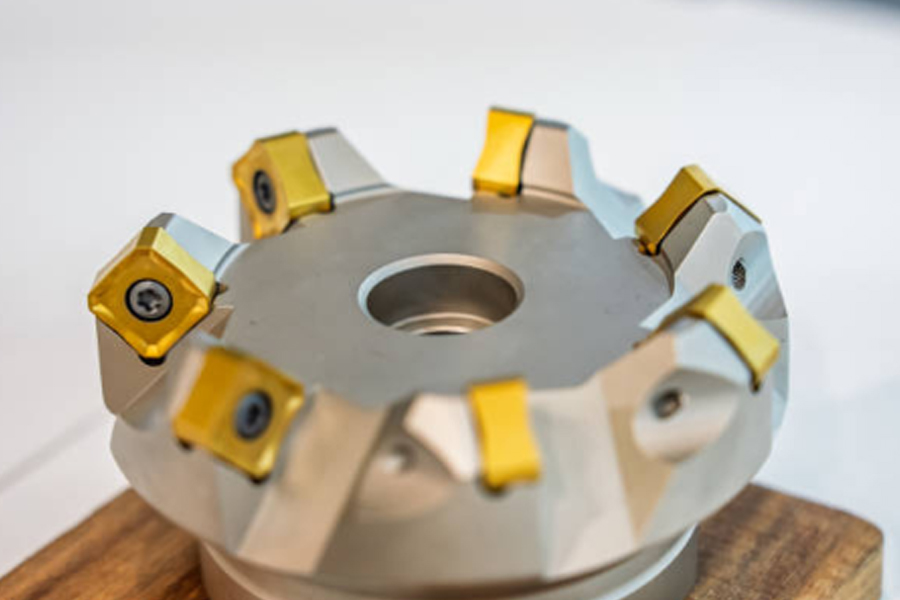
Face Milling Cutters
Face mills resemble short, fat discs. They routinely range from Ø50 mm (2 in.) to over Ø300 mm (12 in.) and carry multiple inserts set at a positive or negative rake. As the spindle rotates, only the inserts on the bottom face engage the material; side flutes do little or no cutting. Because so many inserts cut simultaneously, material removal is extremely efficient. Result: fast stock removal, mirror-flat surfaces, and low tool deflection.
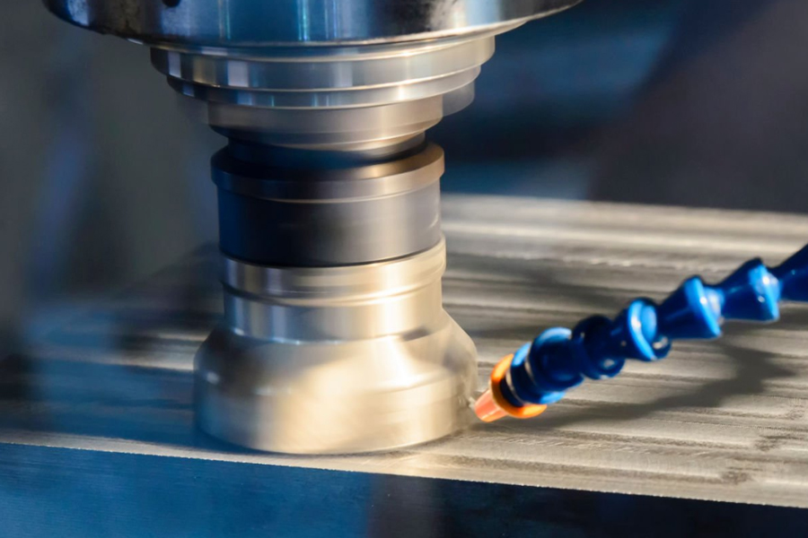
End Milling Cutters
End mills look like elongated cylinders. Flutes spiral up the periphery, allowing the tool to slice sideways, ramp, and even plunge. Geometry varies with purpose:
-
Flat (square) end mill – crisp corners at the tip, perfect for pockets and slots.
-
Ball-nose end mill – spherical tip for 3-D surfacing.
-
Bull-nose end mill – small corner radius to boost strength while still leaving a flat floor.
-
Chamfer end mill – angled tip for deburring and countersinks.
Because an end mill cuts on its sides and its tip, it can approach the work from almost any direction.
Machine Motion and Workpiece Strategy
-
Face milling: The tool or workpiece traverses in an overlapping grid or spiral so the cutter “faces off” an area wider than its diameter. Depth of cut is shallow (0.25–2 mm), feed per tooth is high, spindle speed is moderate to avoid hammering the inserts.
-
End milling: Toolpaths follow the desired feature. Pockets might be cleared pocket-by-pocket, walls profiled with multiple Z-level passes, or 3-D forms sculpted with simultaneous 5-axis motion. Depth of cut can exceed tool diameter in roughing strategies such as high-efficiency milling (HEM).
Surface Finish Comparison
| Parameter | Face Milling | End Milling |
|---|---|---|
| Roughness (Ra) | 0.5–1.6 µm common; <0.2 µm with wiper inserts | 0.8–3.2 µm typical; ball-nose finishing ~0.4 µm |
| Flatness | Excellent; ideal for datum surfaces | Flatness depends on step-over and tool deflection |
| Tool Marks | Arch-shaped cutter marks concentric to tool path | Parallel scallops or “steps” equal to chordal height |
When a customer print calls for a reference plane with 0.05 mm flatness and 0.8 µm Ra, a face mill with polished wiper inserts is the fastest way there. If the part needs an internal fillet or deep pocket floor, end milling takes over.
Material Removal Rate (MRR)
Face mills hog stock rapidly thanks to large diameter and multiple teeth. A Ø125 mm cutter with eight inserts might run 2 mm depth at 0.35 mm/rev feed per tooth—over 1000 cm³/min in aluminum. Equivalent removal with an end mill would overload the tool or spindle.
However, modern HEM toolpaths let small-diameter solid carbide end mills engage 10 × D axial depth at low radial engagement, spreading wear and raising MRR. Choosing face milling for bulk stock removal on open flats, then swapping to aggressive HEM for pockets, often yields the best cycle time.
Typical Applications by Industry
| Industry | Face Milling Tasks | End Milling Tasks |
|---|---|---|
| Automotive | Deck engine blocks, cylinder-head faces | Machine oil galleries, valve pockets, timing slots |
| Aerospace | Create mating pads on spars, ribs | Lightweight pockets, complex bulkheads, 5-axis impellers |
| Medical | Smooth datums on orthopedic fixtures | Mill contoured implant surfaces, slots for fixation screws |
| Electronics | Flat heat-sink contact areas | Tiny pockets for chips, high-speed micro-end-milling |
| Tool & Die | Square die shoes, trim surfaces | Sculpt cavity forms, electrodes, lifter slots |

Cost Considerations
-
Tooling Investment
Face mills generally need an indexable body ($200–$900) plus inserts ($5–$12 each). End mills can be solid-carbide ($20–$150) or indexable. -
Insert Life
Face-milling inserts often rotate to unused edges, lowering cost per edge. Solid end mills must be reground or replaced. -
Machine Time
Face milling can slash setup minutes by preparing datums quickly. End milling dominates longer cycles for 3-D surfacing. -
Changeovers
A single face mill may replace multiple fly-cutters or shell mills. Conversely, a shop may stock dozens of specialized end mills for different corner radii or reach.
Selecting Feeds and Speeds
General rule: prioritize chip thickness, not chip load guesswork.
-
Face Milling Steel (indexable)
Vc = 200 m/min, fz = 0.15 mm/tooth, ae = 80 mm (full width), ap = 1.5 mm -
End Milling Aluminum (solid carbide, flat)
Vc = 400 m/min, fz = 0.08 mm/tooth, ae = 0.5 × D, ap = 1 × D
Always check manufacturer charts and adapt for rigidity, coolant, and tool reach.
Common Mistakes and How to Avoid Them
-
Using end mills for large facing jobs – wastes time; swap to a face mill.
-
Plunging a face mill – risk of tool breakage; face mills are not end-cutting.
-
Ignoring chip evacuation in deep pockets – get coolant nozzles or air blast on the flutes.
-
Insufficient overlap on facing toolpaths – can leave uncut steps; overlap by 20–25 % of cutter diameter.
-
Overloading end mills in corners – use high-speed trochoidal or adaptive clearing to keep engagement constant.
Hybrid Strategies for Cycle-Time Wins
Smart programmers rarely pick only one method. A typical CNC sequence might:
-
Face-mill the blank to establish datums.
-
Rough pockets with a high-feed indexable end mill.
-
Finish walls with a smaller diameter end mill for crisp corners.
-
Perform 3-D surfacing with a ball-nose tool.
Each step uses the cutter style best suited to the geometry and required finish, maximizing efficiency and tool life.
Future Trends—Tooling Gets Smarter
-
Digital twin optimization: CAM software now simulates material removal to suggest when to switch from face to end milling.
-
Variable-pitch cutters: Reduce chatter in lightweight machine frames.
-
Additive + subtractive combos: 3-D printed near-net shapes finished with hybrid face/end-milling heads.
-
Tool-mounted vibration sensors: Automatically adjust feed to protect inserts and extend life.
Staying abreast of these innovations can cut cycle times even further and lower cost per part.
Conclusion
Face milling and end milling are complementary, not competing, techniques. Face mills create broad, flat datums with speed and rigidity; end mills dive into pockets, sculpt curves, and finish features where face mills cannot reach. Understanding cutter geometry, toolpath strategy, and material behavior lets machinists choose the optimal operation—or blend both—for each feature on the print.
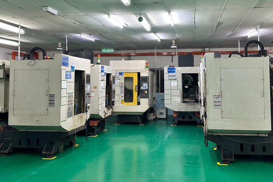
Ares Precision leverages this balanced approach daily, pairing state-of-the-art face-milling heads with a vast inventory of high-performance end mills to deliver tight-tolerance parts in steel, aluminum, titanium, and more. Whether you need blazing-fast datum facing or intricate 5-axis contour milling, our engineers can craft the ideal process plan to hit your cost, quality, and lead-time targets. Ready to optimize your next CNC project? Contact Ares Precision today and experience machining expertise without compromise.