Pemesinan Computer Numerical Control (CNC) ialah salah satu kaedah paling dipercayai untuk menukar bahan mentah kepada komponen logam dan plastik berketepatan tinggi bagi industri aeroangkasa hingga elektronik. Di antara pelbagai proses CNC, pengilangan hujung (end milling) paling serba guna. Dengan satu penyediaan mesin serta set pemotong yang betul, sebuah pusat pemesinan dapat membuang lebihan bahan, membentuk kontur 3-D bebas, dan melicinkan permukaan—selalunya pada kepingan kerja yang sama.
Bagi pakar perolehan, jurutera dan pengilang, memahami asas end milling membantu pemilihan proses, anggaran kos, dan kerjasama pembekal yang lancar. Panduan ini menerangkan definisi end milling, perbezaannya dengan operasi lain, jenis alat pemotong, serta sebabnya ia masih penting dalam fabrikasi moden.
Apakah Itu End Milling CNC?
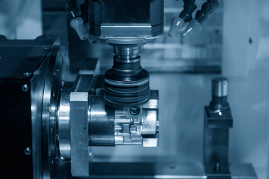
End milling ialah proses subtraktif di mana alat pemotong berputar—dipanggil end mill—menanggalkan bahan daripada benda kerja (pegun atau diselaras servo). Ciri utama end mill ialah tepi pemotong heliks yang dipanggil flute di sekeliling perimeternya. Jika flute bertemu di tengah hujung, alat itu digelar center-cutting; hanya alat sedemikian boleh “menusuk” secara menegak ke dalam bahan.
Kerana alat boleh menyuap secara paksi dan lateral, ia boleh memesin hampir ke mana-mana arah:
- Aksial – menusuk lurus atau interpolasi heliks
- Radial – pemotongan sisi dinding
- Multi-paksi serentak – kontur 3-D kompleks
Analogi mudah: bayangkan mata gerudi yang bukan sahaja boleh menebuk lubang tetapi terus mengukir poket, mengikut dinding kontur, atau memotong perimeter—itulah kuasa end mill.
Perbezaan End Milling dengan Operasi CNC Lain
| Proses | Tindakan Pemotongan Utama | Tujuan Lazim | Had Utama |
| Penggerudian | Alat berputar & menusuk secara aksial | Lubang bulat pantas | Tidak boleh memotong sisi |
| Pengilangan Muka (Face Milling) | Pemotong berdiameter besar menanggalkan bahan terutamanya pada muka alat | Meratakan permukaan luas | Tidak sesuai bagi ciri berdinding dalam |
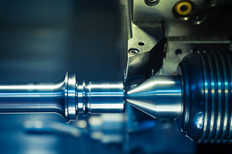
| Pelarik (Turning) | Benda kerja berputar, alat pegun | Bentuk silinder | Terhad kepada geometri paksi simetri |
| Slot Drill / Slotting | “Slot drill” 2-/3-flute memotong salur selebar diameter alat | Slot lebar piawai sekali lalu | Lebar terikat diameter alat |
| End Milling | Alat berputar, boleh gerak aksial, radial, diagonal | Poket, kontur, permukaan 3-D, profil | Perlu pilihan alat & program tepat |
Gambaran Alat End Mill
(senarai dipadatkan—struktur, aplikasi, dan nota sama seperti versi Inggeris)
- Flat (Square) End Mill – lantai rata, sudut 90°.
- Ball-Nose End Mill – hujung hemisfera; sesuai kontur 3-D.
- Bull-Nose End Mill – dasar rata + radius sudut; kukuh untuk poket.
- Chamfer Mill – hujung bersudut 45°/60°; serong & nyah-burr.
- Roughing (Hog) Mill – flute bergerigi “corn-cob” untuk pembuangan material maksimum.
Aliran Kerja End Milling
- Reka Bentuk & CAM – model CAD → pemilihan alat & laluan → G-code.
- Penyediaan Mesin – penjepitan benda kerja, penetapan datum, muatan alat.
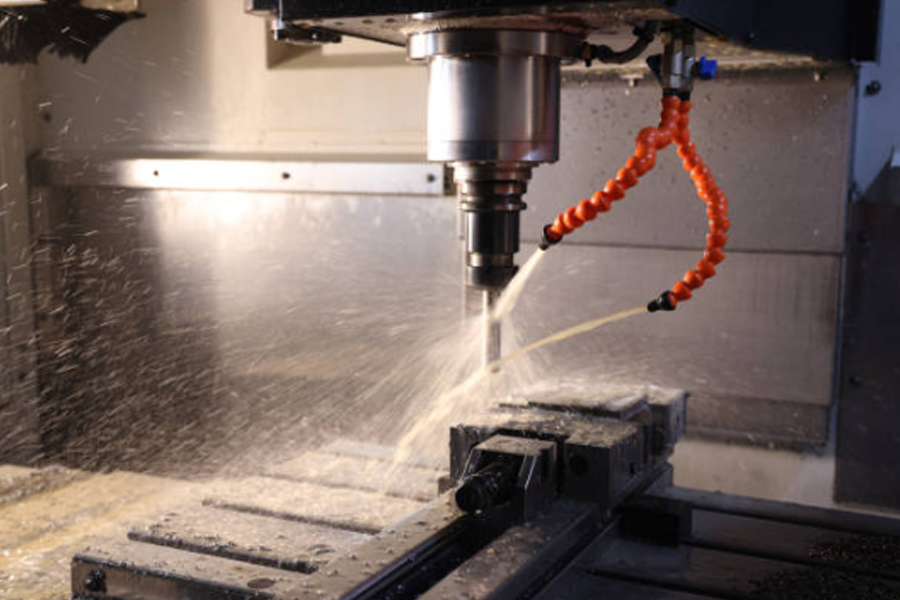
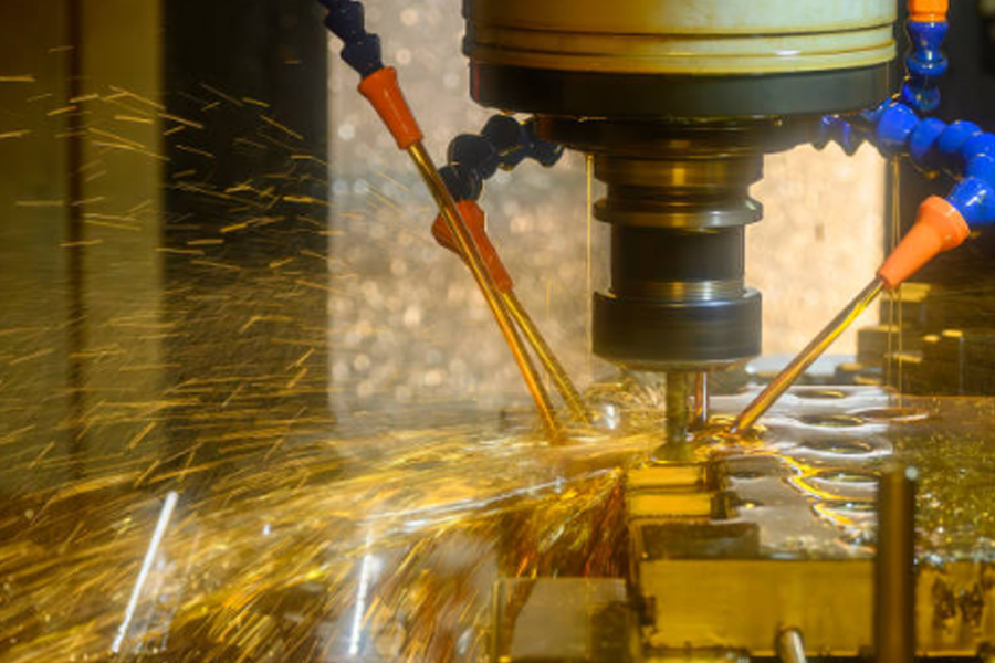
- Pemotongan – putaran ribuan RPM, ketepatan ± 0.013 mm, penyejukan flood / MQL / udara.
- Pembentukan Ciri – poket, slot, profil, kontur serentak 3-paksi/5-paksi.
Kelebihan Utama
- Ketepatan tinggi & kebolehulangan ± 0.0005 in (≈ 0.013 mm).
- Serba guna – 2-D hingga 3-D dalam satu set-up.
- Keserasian bahan luas – aloi Al, Mg, keluli tahan karat, titanium, plastik teknikal, komposit.
- Kecekapan HSM & 5-paksi – masa kitaran pendek, kurang fixturing.
Aplikasi Industri
| Industri | Contoh Komponen |
| Aeroangkasa/ Pertahanan | Rusuk sayap, rangka fiuslaj titanium, bilah turbin 5-paksi |
| Automotif | Blok enjin, acuan stamping panel badan, perumah transmisi Al |
| Perubatan | Implan titanium, sangkar PEEK tulang belakang, panduan pembedahan |
| Elektronik / Barangan Pengguna | Unibody laptop, ‘heat-sink’ aluminium, penyambung RF mikro |
Faktor Kualiti Kritikal
- Bahan & Salutan alat – HSS vs. karbida, TiN/TiAlN/AlCrN.
- Kelajuan & suapan optimum – beban cip betul mengelak geseran / patah.
- Strategi penyejukan & buang cip – flood, through-spindle, MQL + udara.
- Kekakuan mesin & kemahiran operator – mengawal getaran, prob-in-process.
Pertimbangan Reka Bentuk
- Jejari dalaman minimum ≥ jejari alat.
- Jarak capai > 3× Ø memerlukan parameter konservatif.
- Kadar buang bahan – tinggalkan stok 0.5–1 mm untuk finishing.
- Kekasaran permukaan (Ra) perlu ditanda pada permukaan kritikal.
Kesimpulan
End milling kekal sebagai tulang belakang pembuatan CNC—menyampaikan komponen berketepatan tinggi, kompleks dan boleh diulang semula. Dengan alat yang betul, parameter optimum dan rakan kedai mesin bertauliah, projek anda akan lebih pantas, tepat dan menjimatkan.
Perlu bahagian digiling tepat?
Ares Precision (Malaysia)—bersijil ISO 9001—mengendalikan pusat CNC 3-, 4- dan 5-paksi canggih. Jurutera kami menyemak keboleh-bikinan, mengesyorkan strategi end milling terbaik dan menepati piawaian kualiti paling ketat.
Hubungi kami hari ini untuk membincangkan keperluan anda dan melihat bagaimana kemampuan pengilangan CNC kami boleh mempercepat matlamat pengeluaran anda.